Generate control diagrams and cabinet design
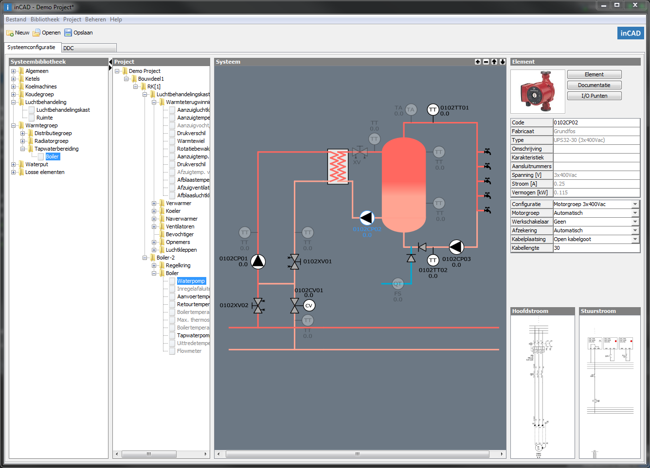
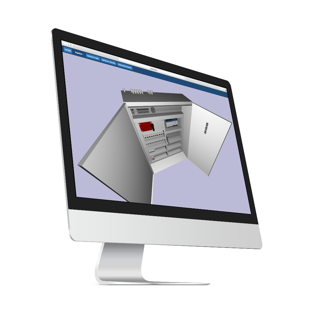
After compiling and configuring the installation, inCAD calculates the required switchgear fully automatically, generates the control diagrams and creates the cabinet design. This process is fast, so that the result can be viewed immediately.
The different elements can be easily coded in a format that can be configured at your own discretion. The code can include the (sequential) number of the control box, the system and/or the digital controller.
Switchgear
The required switchgear is automatically selected by the system. Depending on the type of article, selection is made on properties such as current, voltage, power, number of make/break contacts, characteristic, short-circuit resistance, etc. In this way, the switch material is selected as optimally as possible. The manufacture is easy to change.
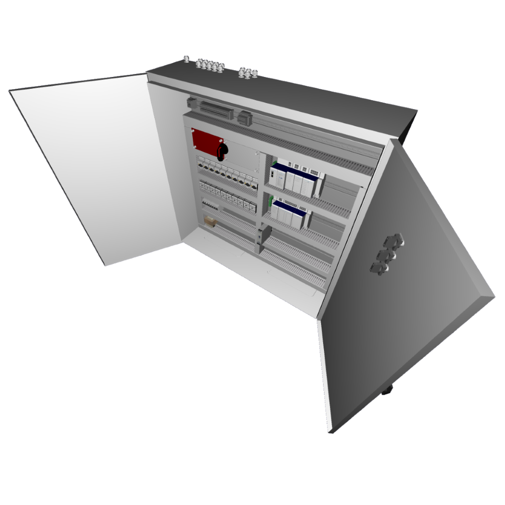
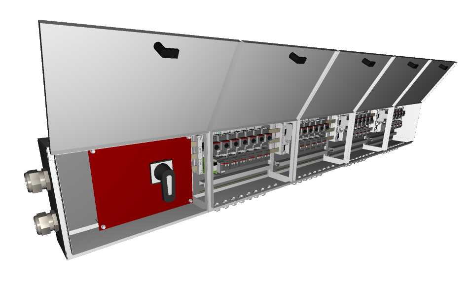
Cabinet design
Depending on the space required and the specified minimum reserve space, inCAD calculates a suitable assembly of control boxes and then arranges them based on a standard template. The user can easily modify this template to adapt the layout of the control box to his/her needs. The heat development in the control cabinet is also determined and cabinet fans are automatically introduced into the design to meet the design requirements for temperature.
Cabling
Depending on the power, cable length and the way in which the cables are installed, inCAD automatically calculates the required cabling for each element in accordance with the NEN-1010 standard. Corresponding cable glands and cable clamps are also selected.
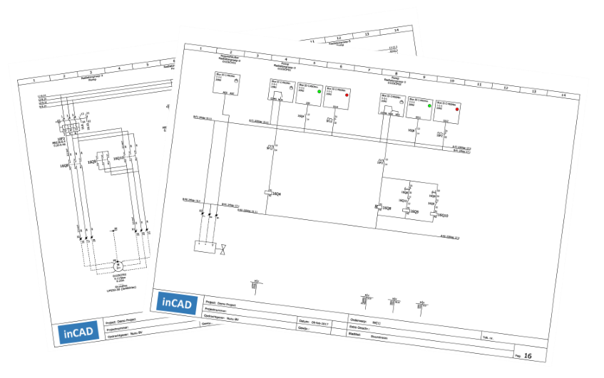
Control scheme
inCAD processes the information provided by the user fully automatically into a complete control scheme containing the principle schemes, main current, control current, material lists, terminal connection lists, cable lists and layout drawing of the control box.


